Finally got my first large format test print. The calibration tests resulted in replacing the 6mm rod used for driving the x axis belts with an 8mm rod and new pulleys. I had the 6mm rod on hand so I thought I could drill out the 5mm bore pulleys which ended up off center by enough to ruin the x axis movement. I also had to replace the 5mm screws for the idler pulley because the threads were causing binding; I found some 5mm bolts with enough smooth area (grip) to fix this.
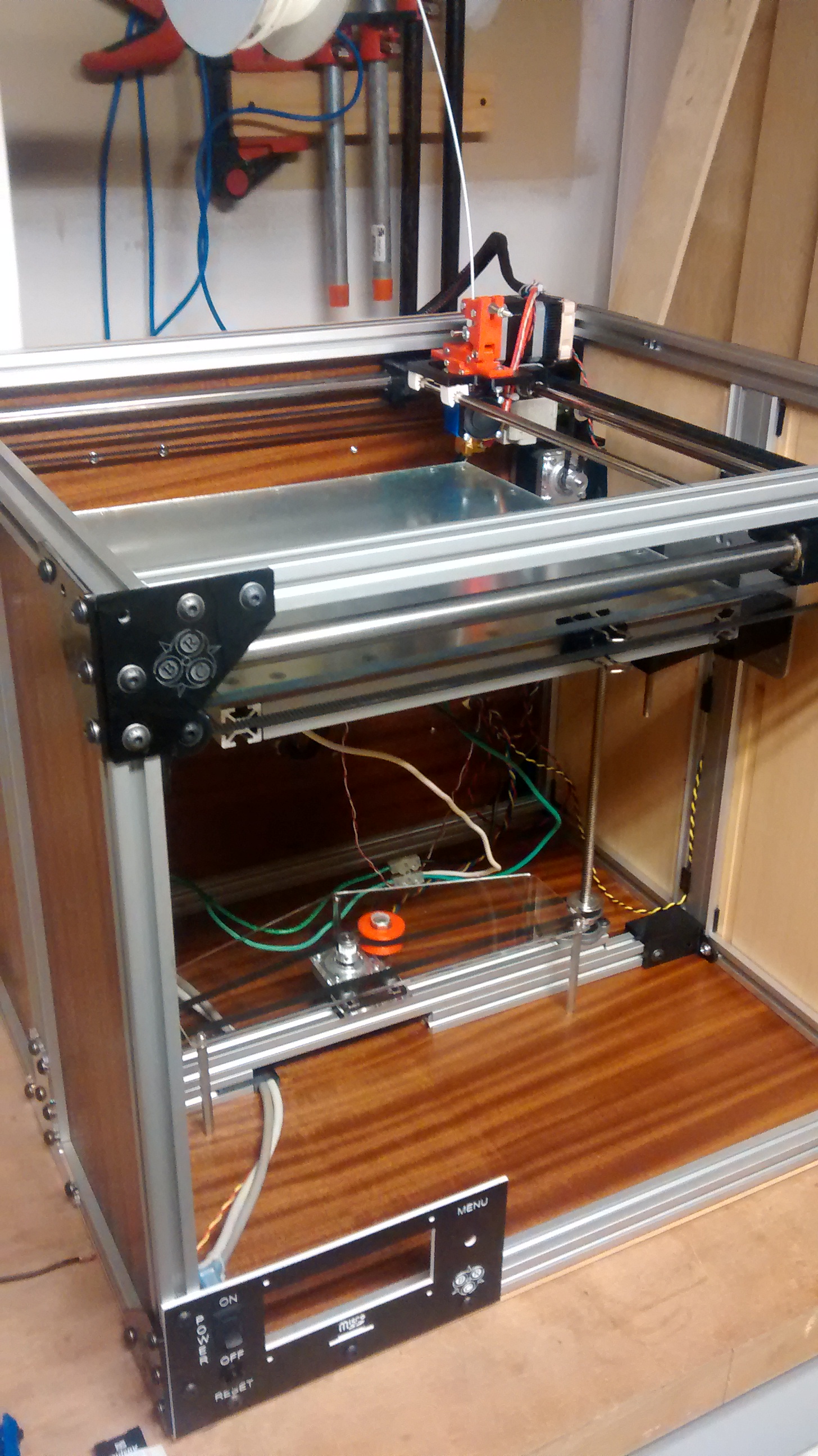
I also had to modify the back right panel to make it easier to adjust the x-axis drive belt. It looked nice inset into the extrusions but I couldn’t make any adjustments without disassembling the entire top half of the machine.
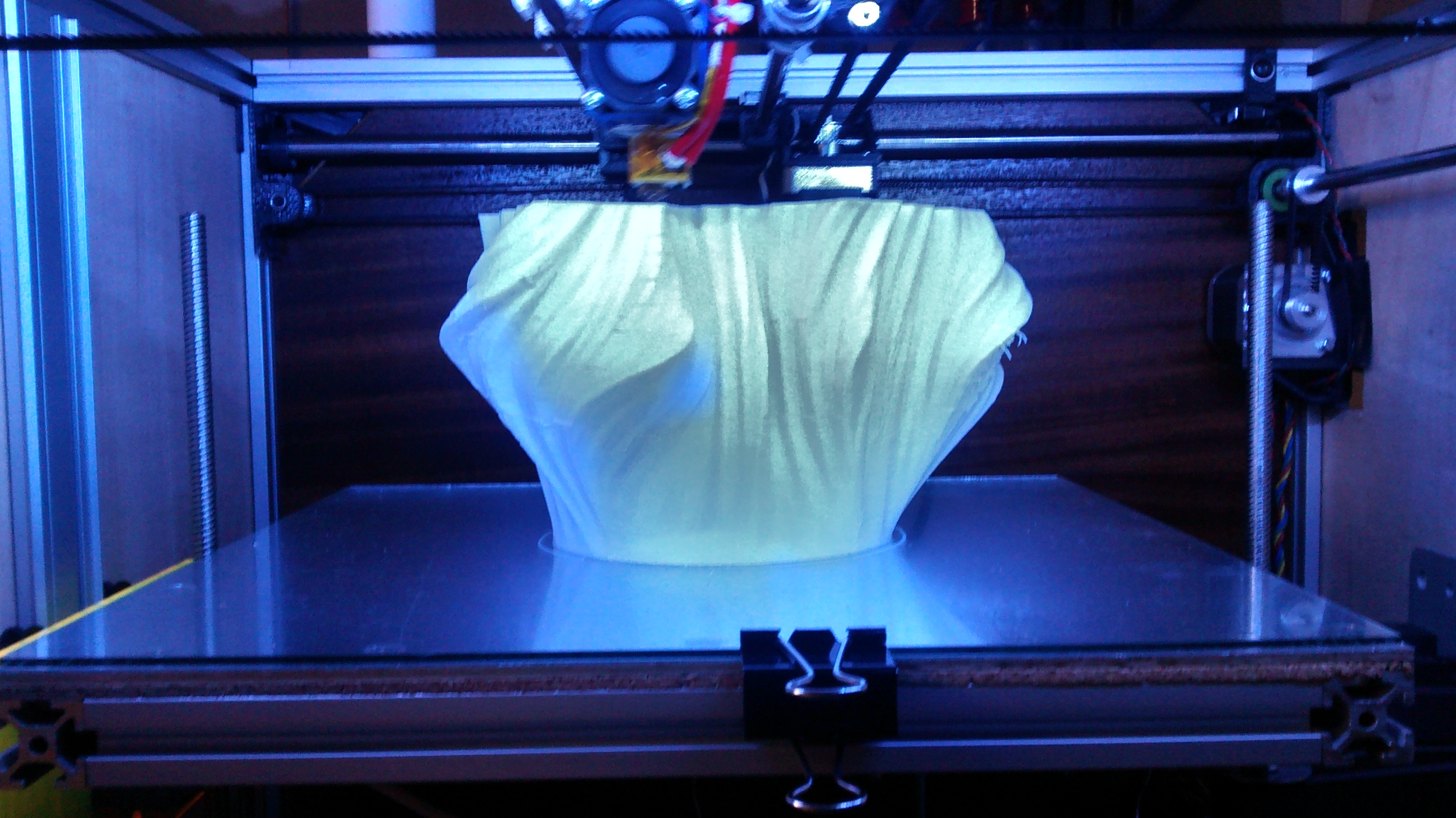
After this major revision, I printed off a vase from Thingiverse with a 2 perimeter wall. The layers began to separate after about 40mm getting worse toward the top. Overall, the print seems to be consistent which means the print head movement is good. Once the enclosure is completed I’ll print another vase with the same settings for a comparison with a heated build chamber.

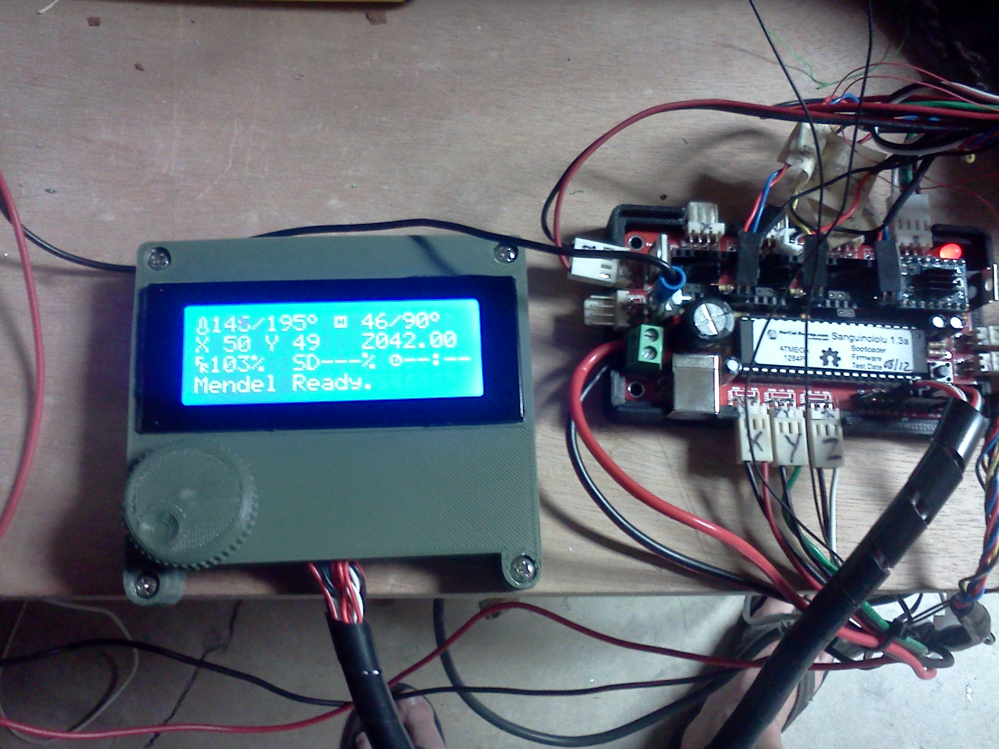
I’ve got some calibration issues.
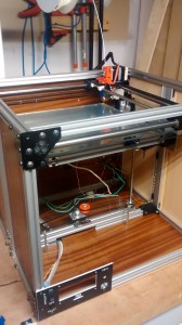
Just need to fix the xy axix calibration, add a roof and front door, and mount a spool holder on the back.

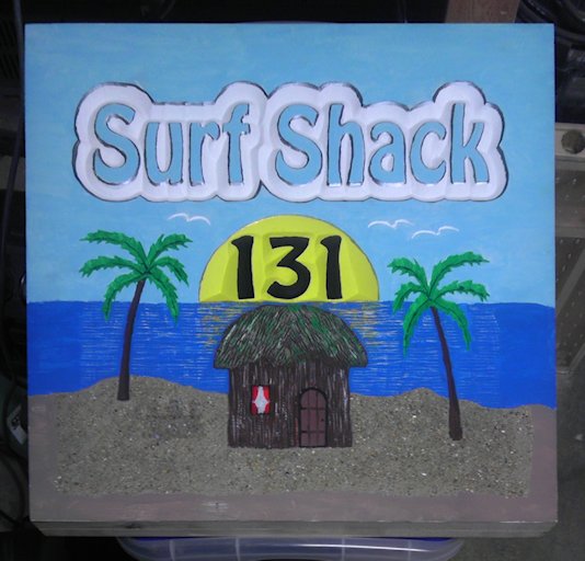
Printed with my Solidoodle 2 speed settings with 2 perimeters. Scaled 150% to 7 x 7 x 9 inches
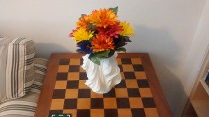
A little filler and a paint job could transform this print into something even better. Cost was about $5.00 in plastic (85 cm3) and 6 hours to print.


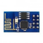 I received two WiFi modules today from

![IMG_20140415_214024766[1]](http://hobbies.boguerat.com/wp-content/uploads/2014/04/IMG_20140415_2140247661.jpg)