I have a Panelolu for my Solidoodle 3d printer. After trying out the .1mm layers I realized that I must have a cooling fan on the print head. I started working on my own I2C solution in January but realized the complexity of the firmware and hardware was beyond my understanding. That is, until I stumbled on the Think3dPrint3d blog where they had already developed a solution dubbed Panelolu 2. I had already purchased a couple MCP23017 i2c chips as well as an assortment of components from Adafruit (LCD, i2c backpack, and MicroSD Breakout). So using what T3P3 has provided on their blog, I put the following panel together that uses i2c and open’s up that valuable pin for the fan.
This project does cost about as much as the Panelolu 2 and doesn’t provide as many options (buzzer, power-on leds). But it can be cheaper if you already have some of these items on hand.
Parts List
Adafruit
$10 i2c/SPI LCD Backpack (https://www.adafruit.com/products/292)
$18 Standard LCD 20×4 (https://www.adafruit.com/products/198)
$15 MicroSD Breakout (https://www.adafruit.com/products/254)
$ 2 Shield Stacking Headers (https://www.adafruit.com/products/85)
Jameco Electronics
$7.60 100766 Female Pin (40)
$.49 103203 8-pin Connector Housing
$.78 163686 5-pin Connector Housing (two)
$1.19 776386 12mm Incremental Encoder
$.35 149948 Tactile Switch
$.95 103271 Right Angle Single Row male headers, 36 position
$.98 103254 8-pin Dbl Row Conn Housing (two) (I had a 6-pin on hand)
OR
$.55 103238 16-pin dbl row housing (instead of two 8-pin housings above)
Cabling options
$4.75 643831 10′ 28AWG Flat ribbon cable (grey)
$6.49 643532 10′ 28AWG Flat ribbon cable (multi-color)
So that’s about 62 dollars plus shipping compared to 45 dollars for the Panelolu 1 plus shipping. If you reuse your Panelolu LCD, SDSS, and encoder board, you would only need the LCD backpack, stacking headers, 16-pin dbl row connector, and 5-pin right angle male header. The Panelolu 2 is about $68 with shipping on eBay.
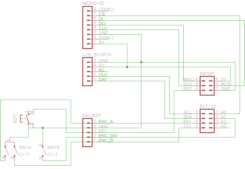
Alright, here’s a schematic for the connections:
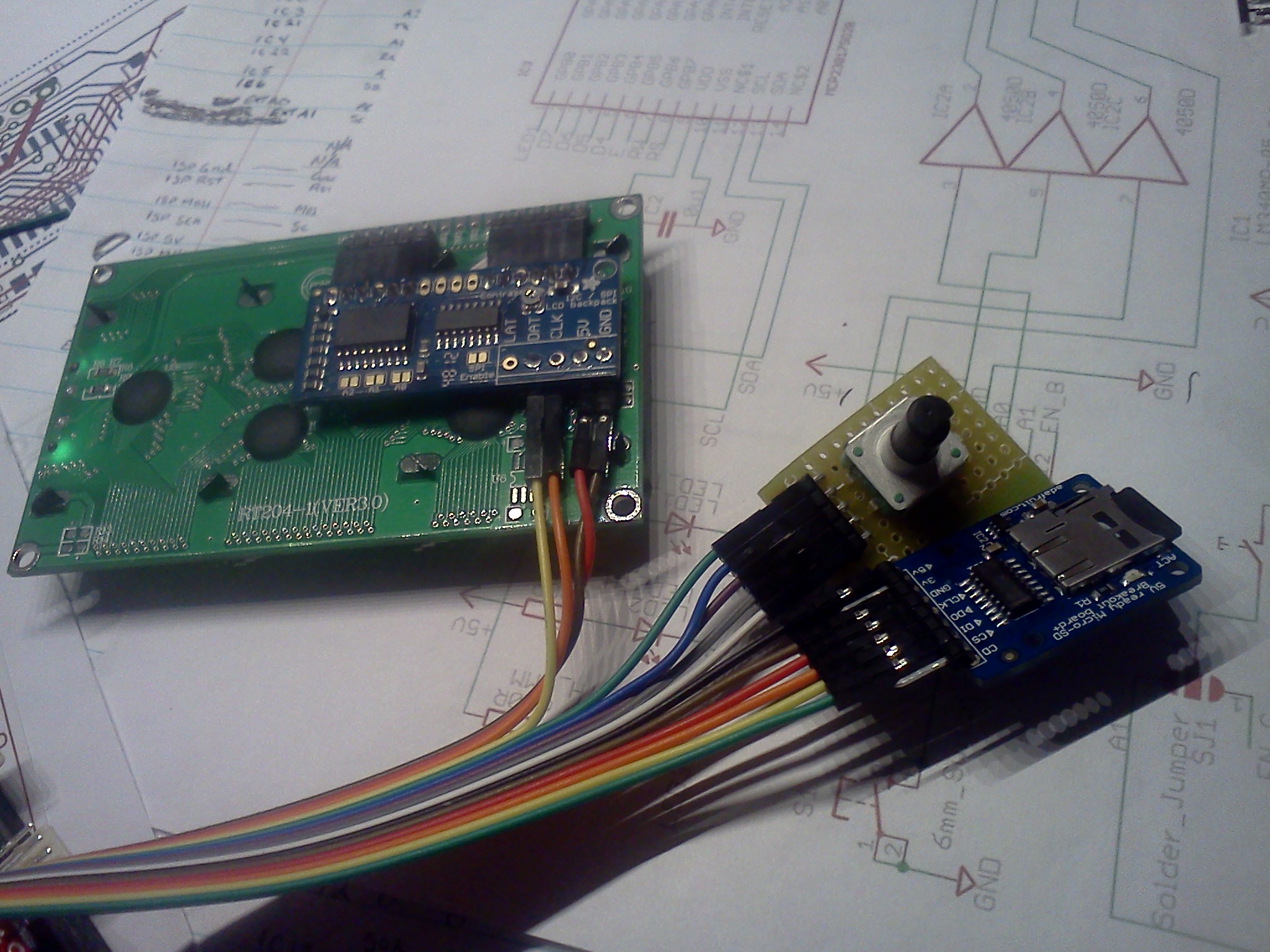
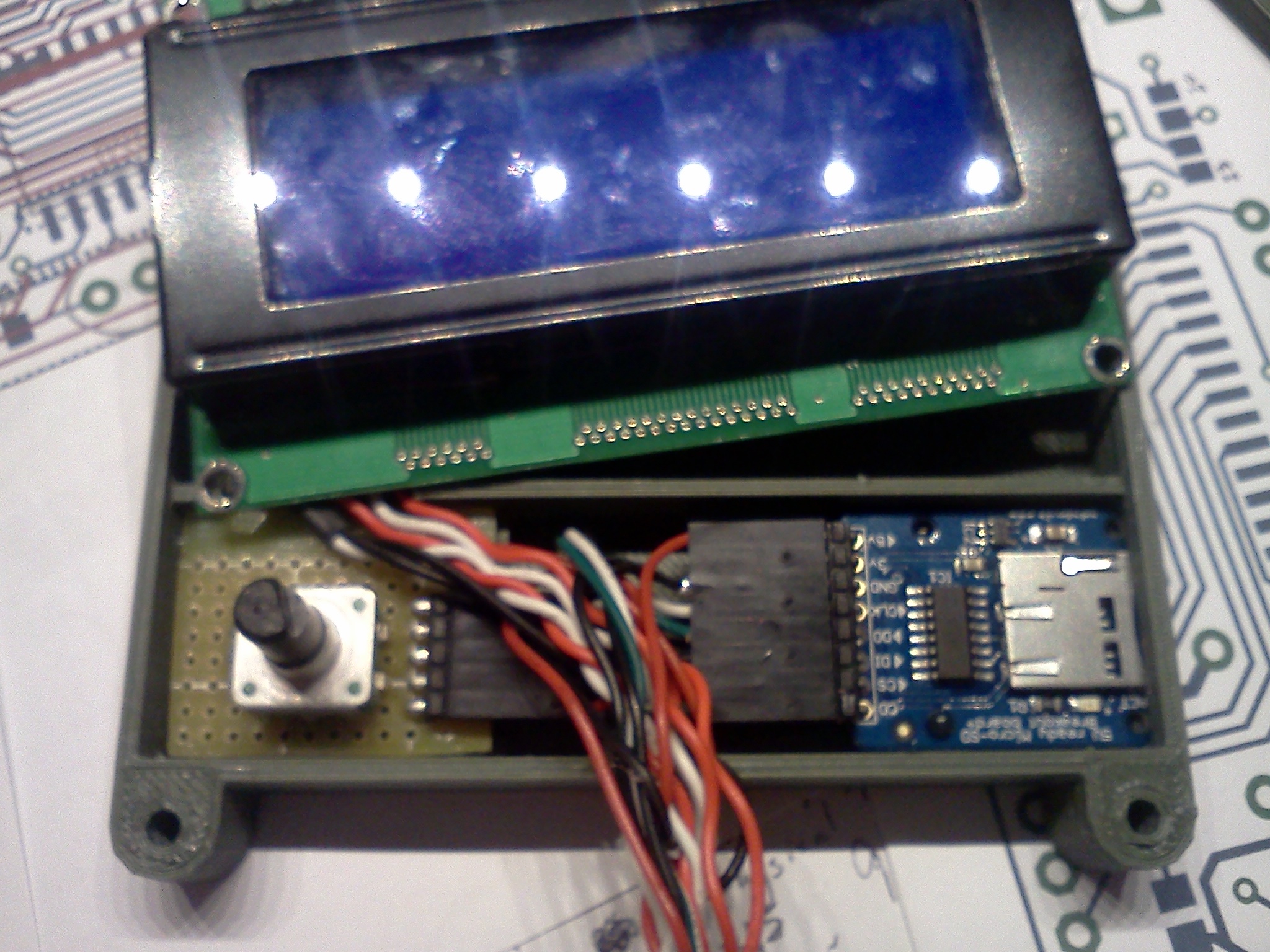
And what it looks like, roughed together:
THE HARDWARE PREP
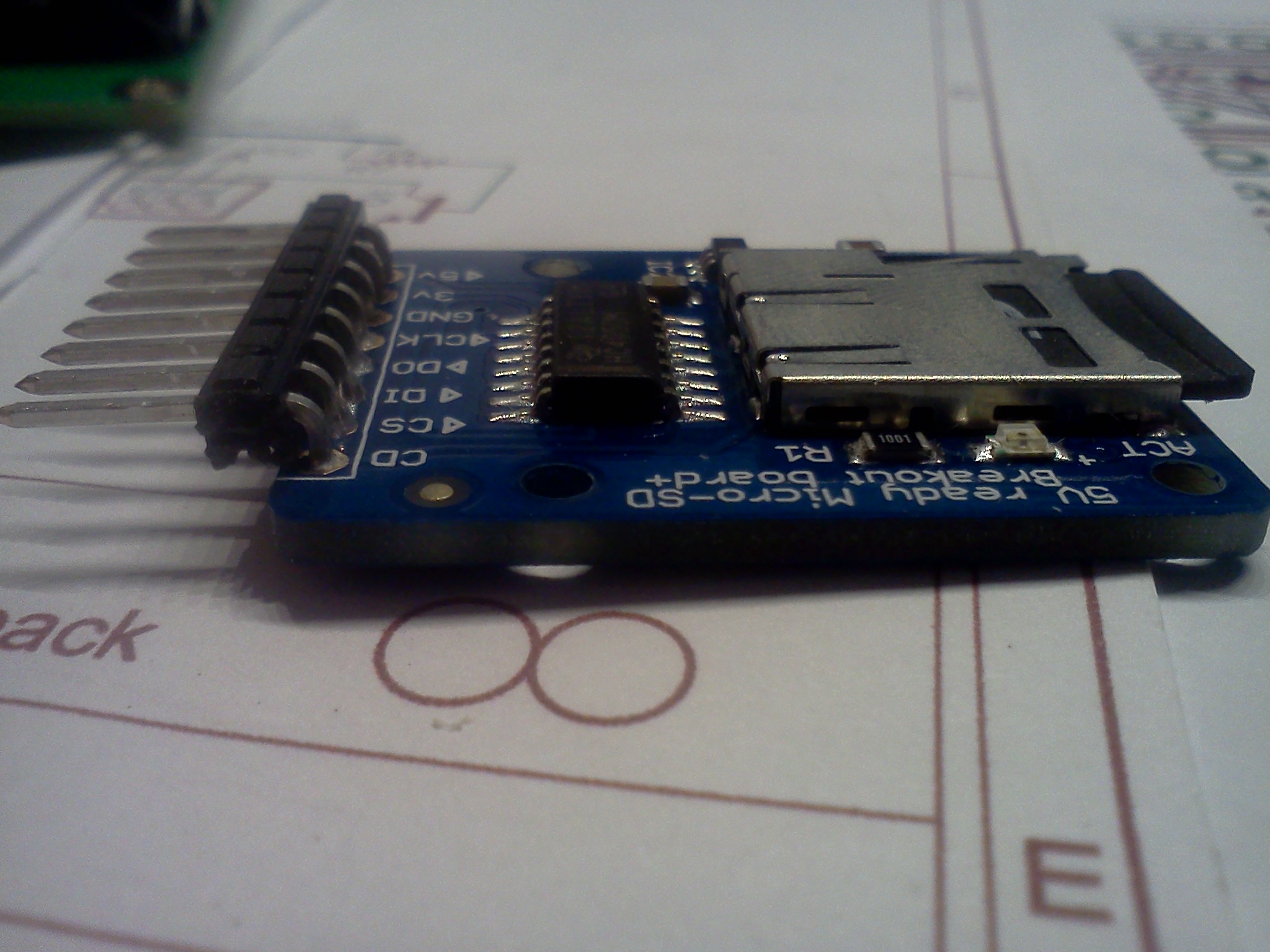
MicroSD Breakout Prep – solder right angle headers.
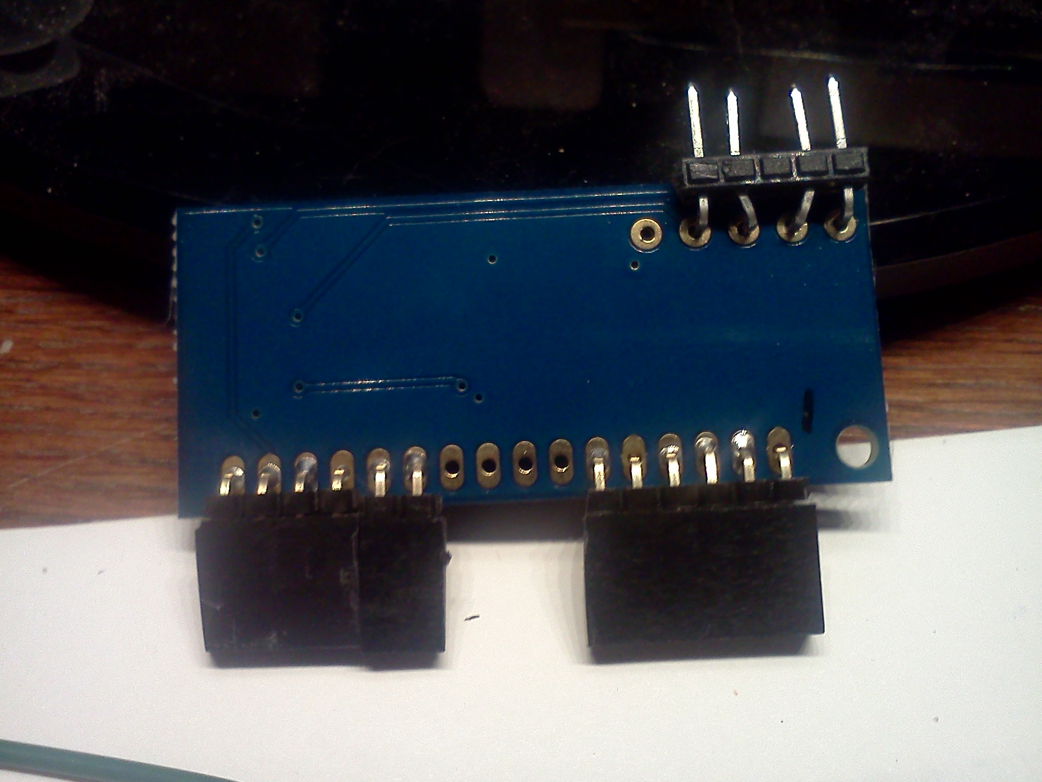
i2c Backpack Prep – Bend the female shield stacking headers 90 degrees and solder two sets of 6 to the outboard 6 holes. Use a row of male headers to hold the female headers in-line while you solder. The header pins should be inserted through the back so that they are soldered on the same side as the ICs.
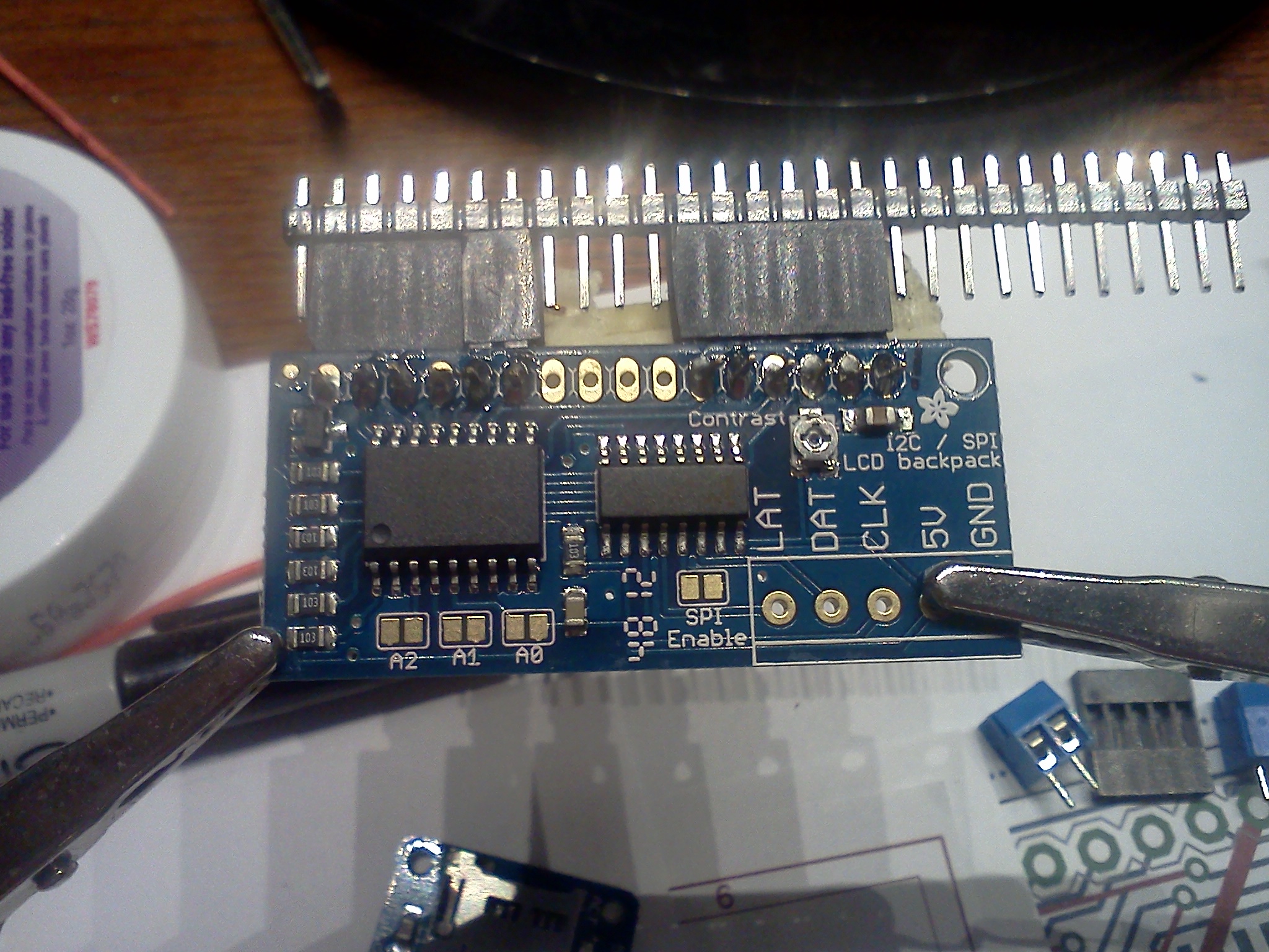
i2c Backpack Prep – Take 5 pins from the right angle header, remove the center pin, push the #2 & #4 pins out a little bit and bend them inward so that they line up with the CLK and 5V holes then solder them in place.
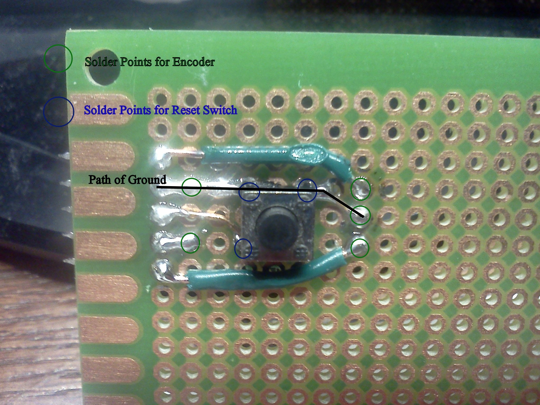
Encoder & Reset Prep – Obtain some perfboard. I put the reset button under the encoder to save space and I had the tendency to inadvertently hit the reset on the Panelolu. You can see below where I connected everything. It was difficult to solder the reset button since it was mounted on the copper pad side, i melted the housing a bit.
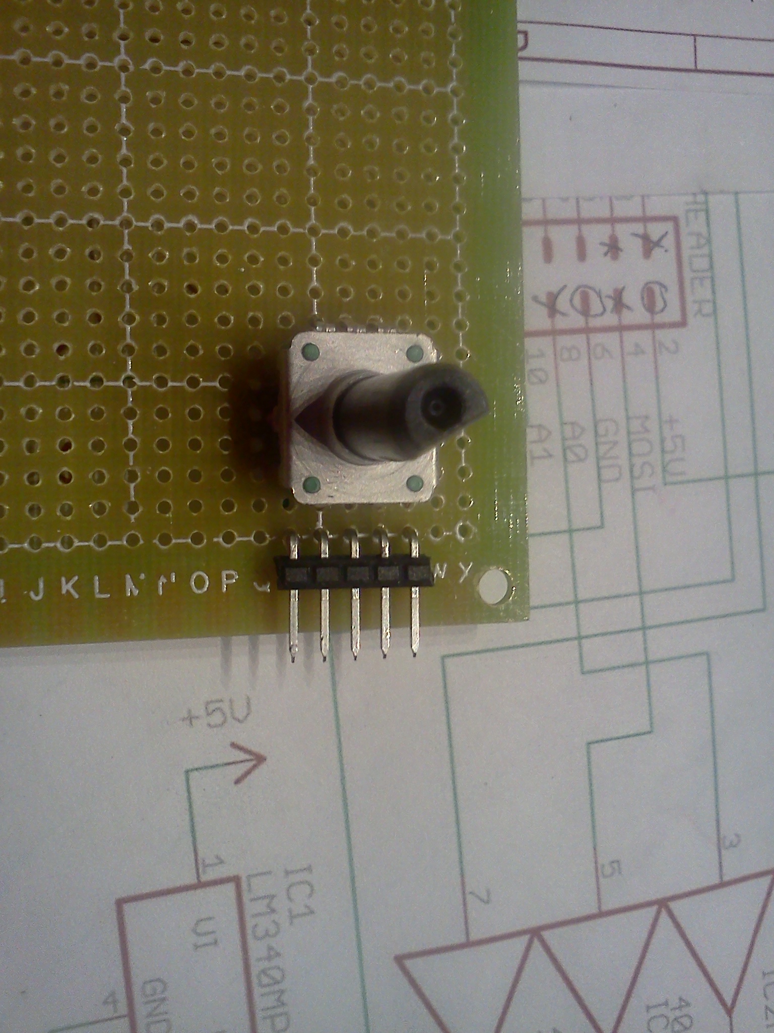
Encoder & Reset Prep – Cut the perfboard down to size.
THE HARDWARE ASSY
Slide the i2c Backpack onto the LCD as shown. Create your wiring harness per the schematic and your type of cabling. Adafruit’s Female/Female jumper wires (28AWG) (https://www.adafruit.com/products/266) are used in the picture below just to make sure it was working.
I reclaimed some USB and 1394 extension cable from a computer panel. The wire was 24-28 AWG and about 3 feet in length. I was getting some kind of interference or bad connection that would garble the text on the LCD. I went back to the Adafruit jumper wires and it worked perfectly. My Panelolu also has episodes of a garbled screen and has a 3 foot cable. I had some 18″ wire that that I bundled together and finally I am up and running with some usable length. I’m starting to think I’ve got some bad connections in the other cables that is causing the problems on-screen. I’ll have to go back and check them.
THE FIRMWARE CHANGES
The lastest version of Marlin on Github has been updated to work nicely with i2c. I’ve made all the changes for my Solidoodle and have made it available. Download the firmware from here and make any changes particular to your machine such as steps/mm, endstops, etc.
Compile and upload to your board.
NO PANEL IS COMPLETE WITHOUT A CASE
I modified the Panelolu 2 .scad file to create my own version without the buzzer, LEDs, and lettering. I also placed the encoder and reset holes on the left side. You can get my version of the OpenSCAD file here. To move the holes for the encoder and reset, just change the appropriate x,y variables. I hacked it apart pretty good so if you want to make significant changes, you’ll either need a good understanding of OpenSCAD or try downloading the original file from Thingiverse to start with that one.
Hot glue the MicroSD in place so that the edge of the board is flush with the outside of the case, and hot glue the encoder board. I was going to buy small screws but this worked out really well. Fit the two halves together ensuring the wires exit through the access hole at the bottom.
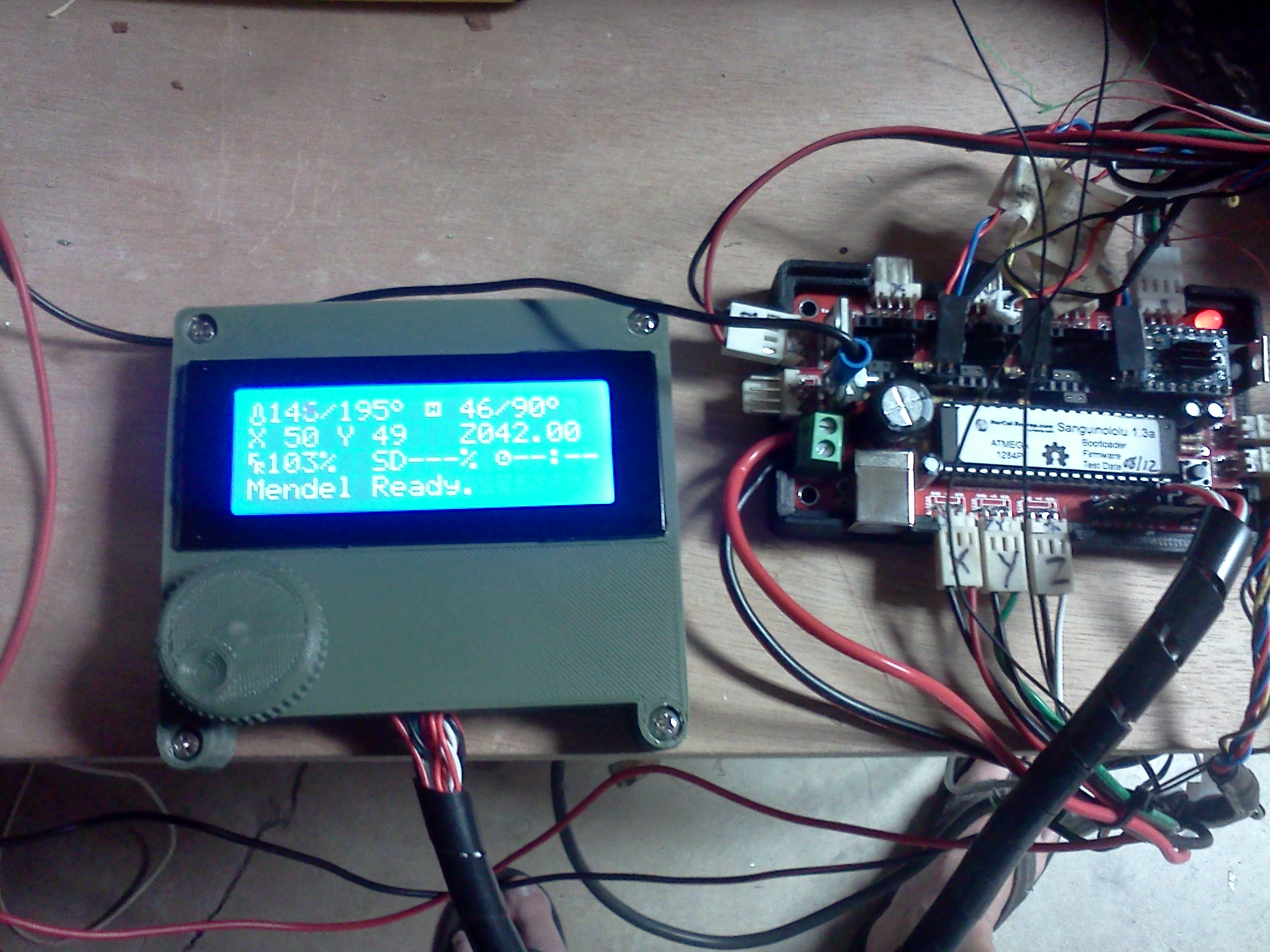
and a quick video of the assembled panel in action: (no sound)
Updated this page with a link to firmware with all the changes made to support this setup.