Doll Beds – But don’t tell anyone I know how to sew…

My daughter was looking at some doll beds in a catalog, you know, the one with the $350 car.  So back to the garage for a little woodworking.  I managed to get some good detail on the headboard and rails with a beading bit on the router. This is also the first time I used traditional mortise and tenon joinery; they just don’t make pocket screws small enough for a project like this.  The post feet and caps were made on the 3d printer to save me some time.  Before I had the printer I probably would have bought or made a small lathe to turn out the small parts.

Worked out great, I printed extra parts so she can split the beds into two singles.  We spent some time with a Singer hand-held sewing machine and some fabric to make a couple mattress covers and pillows. YouTube showed us how to close up the pillows so that the thread didn’t show at the seams.

Baby girl is happy, daddy’s happy.

IMAG0707

Doll Bunkbed

Winter Break Project

Ally and I were watching Tommy MacDonald build some bird houses on Rough Cut and decided we’d do something creative today.  Off to Lowes for supplies and in a couple hours, Ally learned how to use some power tools and we have the yard ready for the birds when they return in the spring.

No paint - no frills, just pure bird house they way they like it.

No paint – no frills, just pure bird house they way they like it.

Junior Woodworker

Junior Woodworker

Vortex style chip separator

I just bought a new filter for my shop vac and after one session with the planer it was caked in dust and chips.  Tired of cleaning this out, I decided I would make a chip separator to keep the bulk of the material away from the VAC.

The 3d Printable parts and instructions are located over at Thingiverse.

Vac Seperator 2

Left Hose – Intake
Right Hose – to Shop Vac


Vac Seperator

Catches the bulk of the sawdust and chips.


VacSep4

After filling up the separator, just a little dust in the bottom of the Shop Vac and the filter was clean.

3d Scan – Wrap up.

Eventually the chair caster wheels had to be replaced with a lazy susan bearing.  The lift was working pretty good but I had to play with the output settings a little bit to prevent it from moving too quickly downward.

Overall, I think this would eventually work but the camera would lose track of the person if it moved too high.  I need to add a tilt mechanism to capture the top of my head, the automatic hole filler in Skanect would leave a dimple instead of a dome.  Everything was just too finicky to keep going.

I was able to get decent enough results but not good enough to warrant purchasing the software.  I might revisit this project but if I do it will probably be to create a camera dolly that rotates around the person. 

3dScan – Lift Motor Drive

I was able to finish up the drive for the vertical movement.  The motor pulls the trolley up via a pulley.  Movement up is very slow and I had to PWM the the downward travel to even things out.  I definitely need to get a better motor if I manage to get decent scans with this rig.

The first worm gear was too rough, I had printed it at .3mm.  The new one is printed at .1mm and that makes a big difference in noise and motion.  I had to run a pulley at the top to double up the line and roughly halve the load on the motor.  Still printing off the end-stop mounts but here’s a shot of where I am on the drive mechanics.

IMAG0657

3dScan – Scanner Lift Motor Drive

Received some parts from Digi-Key to assemble the motor controller for vertical drive that will move the camera.  The controller is basically a relay that has the two outputs crossed so that when the relay goes from Open to Closed the output polarity is reversed.  Two darlington transistors allow control the direction and turn the motor on/off via the Arduino.  I pulled the info from Instructables.  One thing I didn’t check before I heated up the iron was the schematic for the relay. Apparently mine was a little different and I had to do a little rework to get it right.

IMAG0658


T

The motor was pulled from a DVD player/VCR combo that says “Loading Motor” on the PCB.  I’ve been running it at around 9V and it is too fast.  I’ll have to implement PWM to get the speed under control.  I tried a 10k ohm variable resistor but that is too touchy to get the right speed.

I have a worm gear printed off and I need to design a mount for the gear, motor, and spool. Looks like I’ll be busy for a few more days on this.

3dScan – The Draft Code

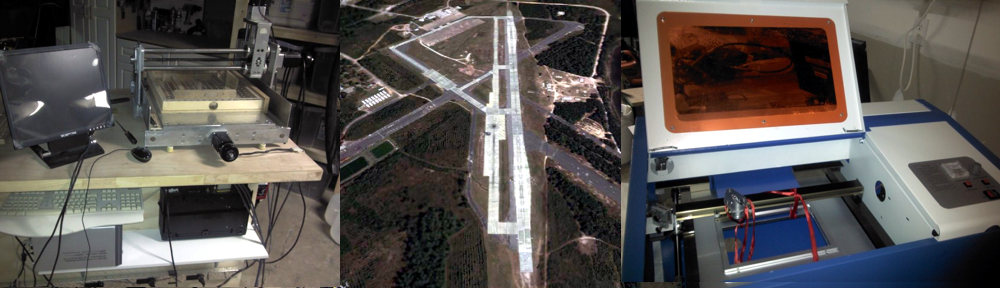
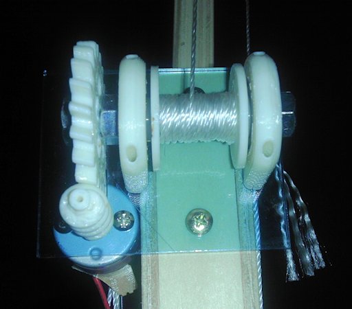
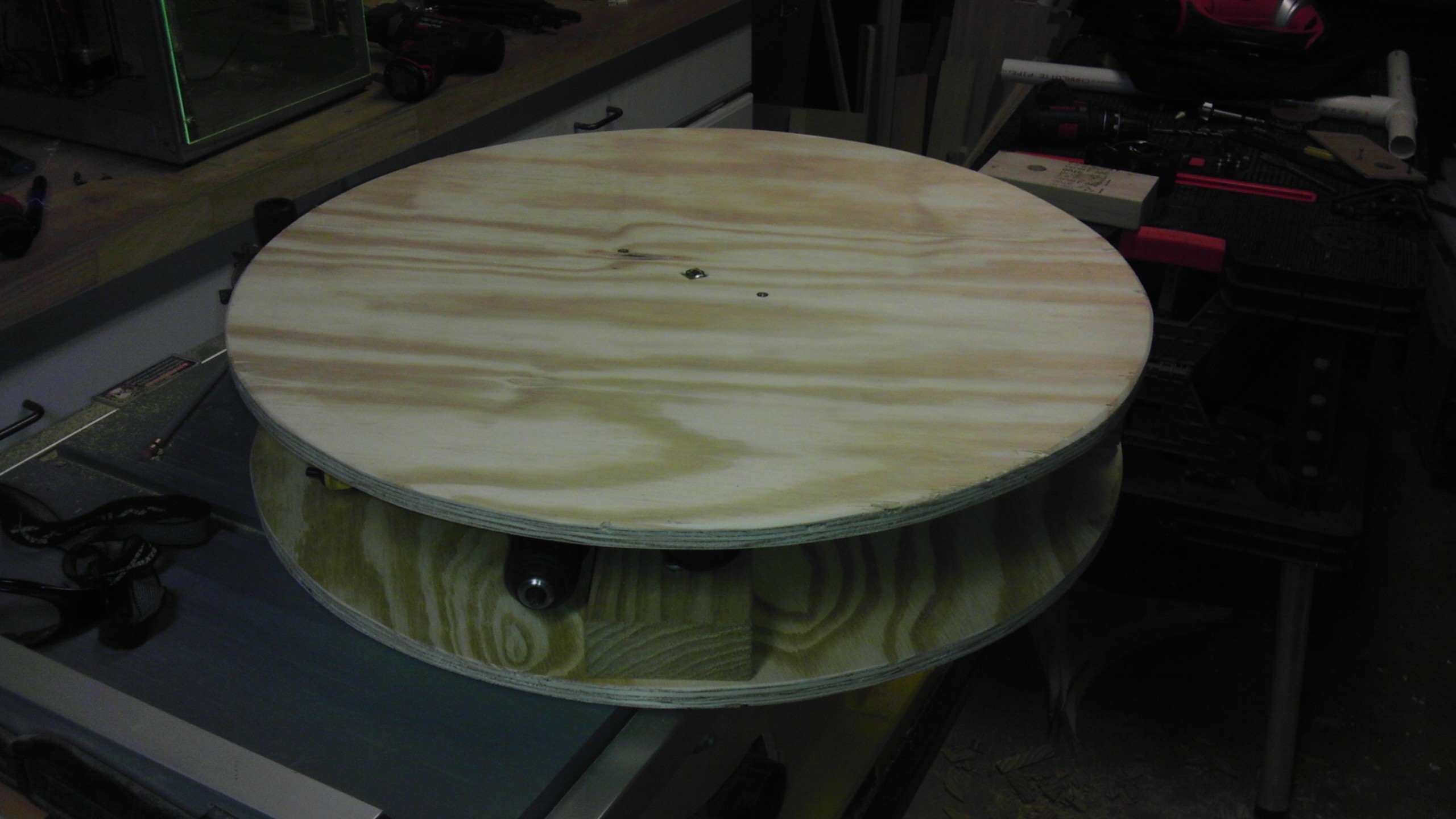
I’ll be using an Arduino UNO to set up the motors on a 1.1 minute cycle to correspond to the max time Skanect runs a scan.  The turntable will simply rotate for the duration.  The Kinect scanner will begin at center then rise until the endstop is activated then reverse direction to the bottom until the endstop is again activated.  Ideally the turntable and scanner will return to their starting position to minimize any manual resetting of the gear between scans.

The initial arduino code is below.  No timer has been implemented as of yet.  This is working on the breadboard and I’m slowly adding the external motor control circuitry.

Open Body Skanner controller
/*The circuit:
* Skanner motor control attached to pin 6
* Skanner direction control attached to pin 7
* Turntable motor control attached to pin 5
* Power button attached from pin 2 to +5V
* 10K resistor attached from pin 2 to ground
* 2 endstops attached in series from pin 3 to +5V
* 10K resistor attached from pin 3 to ground
*/
// Assign pin numbers, using PWM pins for possible use of PWM for speed control
const int powerPin = 0; // the start/stop pin 10k resistor to ground. (pin D2)
const int endStopPin = 1; // the endstop pin 10k resistor to ground. (pin D3)
const int motorPin = 6; // the scanner motor pin
const int dirPin = 7; // the scanner direction pin
const int revolvePin = 5; // the platform motor pin
const unsigned int DEBOUNCE_TIME = 500; // Using 500 to ensure endstop has time to disengage after dir change.
const unsigned int RUNNING_TIME = 60000; // Total running time for each cycle (not implemented)
// Variables
int running = 0; // 0 - off; 1 - on; To start and stop the motor
int dir = 0; // 0 - up; 1 - down; To change direction
long startTime = 0; // time the cycle began.
int actionPending = 0; // 0 - no; 1 - yes: Need to handle the interrupt
long lastStateChange = 0; // Last time the button was pressed
long lastEndStopHit = 0; // Last time the endstop was hit
void setup() {
attachInterrupt(powerPin, stateChange, RISING);
attachInterrupt(endStopPin, dirChange, RISING); // must be rising else no dir change
pinMode(motorPin, OUTPUT); // toggle the pin for motor direction wind the spool
pinMode(dirPin, OUTPUT); // Used to control motor direction.
pinMode(revolvePin, OUTPUT);// Used to control the platform revolution
}
void reverse() { //endstop hit
if (dir == 0) {
// Set pins so motor goes down
digitalWrite(dirPin, HIGH);
dir = 1;
} else {
// Set pins so motor goes up
digitalWrite(dirPin, LOW);
dir = 0;
}
}
void toggleMotion() { //Start up or shut down the motors
if (running == 0) {
// code to start moving the motors
digitalWrite(motorPin, HIGH);
digitalWrite(revolvePin, HIGH);
running = 1;
} else {
// code to stop moving the motors
digitalWrite(motorPin, LOW);
digitalWrite(revolvePin, LOW);
running = 0;
}
}
void endCycle() { // reset to default settings (timer not implemented yet)
digitalWrite(motorPin, LOW);
digitalWrite(revolvePin, LOW);
digitalWrite(dirPin, LOW);
running = 0;
dir = 0;
}
void loop() {
if (actionPending == 1) { // Toggle on/pause
toggleMotion();
actionPending = 0;
}
if (actionPending == 2) { // Toggle direction
reverse();
actionPending = 0;
}
}
void stateChange() { // start/pause motion
long currentTime = millis();
if(currentTime - lastStateChange > DEBOUNCE_TIME) {
actionPending = 1;
}
lastStateChange = currentTime;
}
void dirChange() { // endstop hit, change direction
long currentTime = millis();
if(currentTime - lastEndStopHit > DEBOUNCE_TIME) {
actionPending = 2;
}
lastEndStopHit = currentTime;
}

3dScan – Turntable

The Battery pack has been replaced and wired to accept a 5.5mm jack.  Without the batteries holding the top connector in place, I insulated the connections with tape and then pressed paper filler into the cavity behind the connector.

batterypack2


The turntable came together in a few hours.  I still need to develop a drive system.  I am thinking about using an old gear from a “Wade’s Geared Extruder” thing.  I’ll have to design a track to run the perimeter of the turntable for the gear to turn and hold the top.  Here’s some shots of my progress so far.

tablebase3 tablebase2 tablebase1


The table is 23.5 inches in diameter in 3/4 inch plywood.  The chair caster wheels will support the weight of the average person.  A 5/16″ bolt through the top and into the base with a 608 skate bearing holds the top disk on center.  The top was flexing a little bit so I may double up the thickness later if it becomes a problem.


3dScan – Platform drive

I have an old 9.6V Dewalt drill with dead batteries.  This will make a perfect drive motor as the clutch will prevent the platform from turning when turned off and the motor has variable speed.  The only challenge will be to figure out the drive train.

But first I need to convert the drill to run off power.  I could just buy another battery but that in itself would cost over $40 and my goal is to spend as little as possible.  Also I believe I can control the speed via PWM by using a MOSFET driver and a DC Adapter.

batterypack1


With the battery pack disassembled, I’ve installed a 5.5mm jack to match the 9.5 volt adapter.